PCB CREEPAGE CALCULATOR
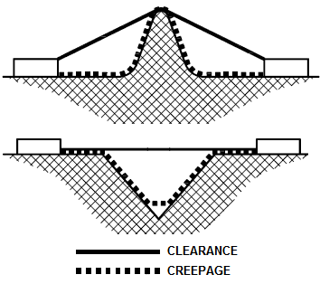
| WHAT IS CREEPAGE? Unlike IPC requirements that deal with electrical clearance, IEC and UL additionally specify so-called creepage. The former is a distance between PCB conductors through air, and the latter by definition is shortest path between two conductive parts, or between a conductive part and the bounding surface of the equipment, measured along the surface of the insulation. The diagram below shows examples of measurement of both quantities. The creepage requirements depend on the insulation material group, pollution degree and working voltage. For a given circuit and application, these requirements are always greater than or equal to the clearance. Our calculator provides the values from Table 2N of UL60950-1 2nd Edition. The Table 17 of the new IEC 62368-1, which replaced 60950-1 in 2020 provides the same requirements for frequencies up to 30kHz. Note that these values apply to functional, basic and supplemental insulations. For reinforced insulation you need to double the results. |
|
|
 The pollution degree depends on your intended application. Degree 1 means no pollution or only dry non-conductive one. 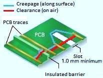 Creepage distance can be increased by adding an insulated barrier or a slot wider than 1 mm (see diagram).
For circuits not covered by safety requirements see calculator of trace spacing between tracks in internal and external layers per IPC2221B and IPC9592B. |